4 - Modelling the existing network

Written by Cody Yakimoff
Updated at December 20th, 2022
Table of Contents
Now that the construction libraries and the project has been setup, you can begin modelling your network.
Using the Pole tool
Adding poles
- Select the Pole tool on the toolbar
- Select Pole type on the Properties panel on the sidebar
- Left-click to place a pole of that type down
- Continue to click to place additional poles of the same type
Removing poles
To remove a pole, left-click it (or select multiple poles) and press DEL / DELETE on your keyboard.
Modifying poles
You can modify individual or groups of selected poles. In this example, we will modify a group of poles at once.
Left-click and drag to select multiple poles, and on the Properties panel in the sidebar select Set Type to change them to a different pole type:
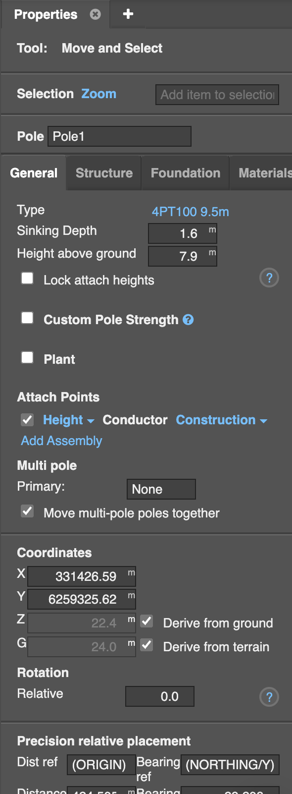
Select an individual pole to change its detailed characteristics using the options that appear in the Properties panel in the sidebar:
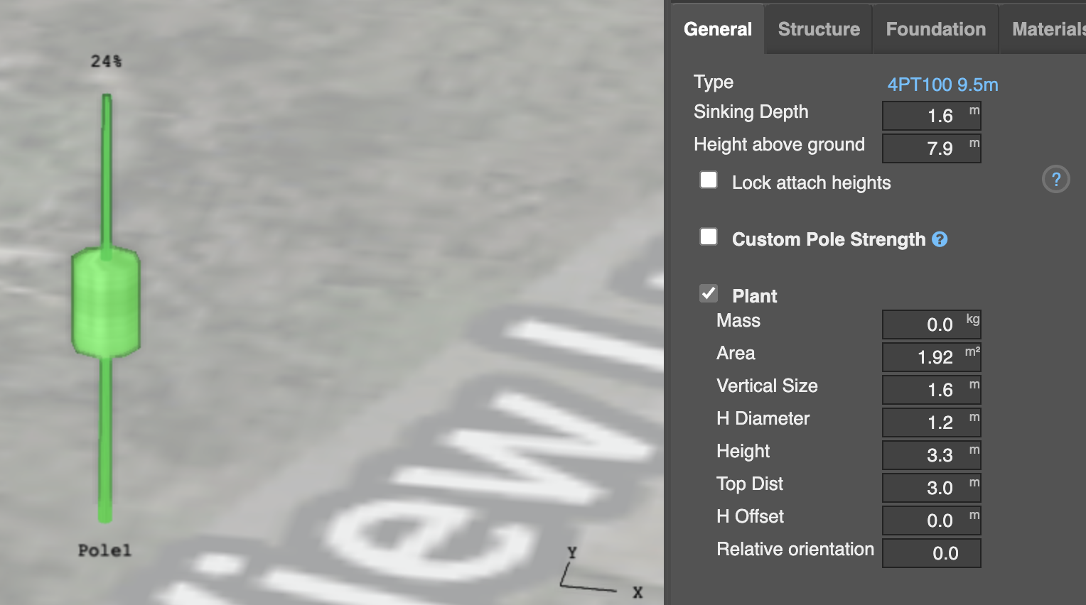
While selected, you can also add a transformer/pole top substation by ticking the Plant checkbox under the General tab, and adding your specification.
Using the Conductor tool
With the Conductor tool you can:
- Click to place a pole and a conductor attached; or
- Click on an existing pole to string a conductor to that pole.
Stringing conductors across poles
In this example we have existing poles placed, so will simply string them up with conductors:
- Select the Conductor tool on the toolbar
- In the Properties tab on sidebar select the Conductor and Construction types to use
-
Left-click on existing poles to string the conductor across them
- If you left-click on an empty space it will place and string a new pole automatically
- Right-click to stop stringing conductors or placing poles
Viewing and editing conductor properties
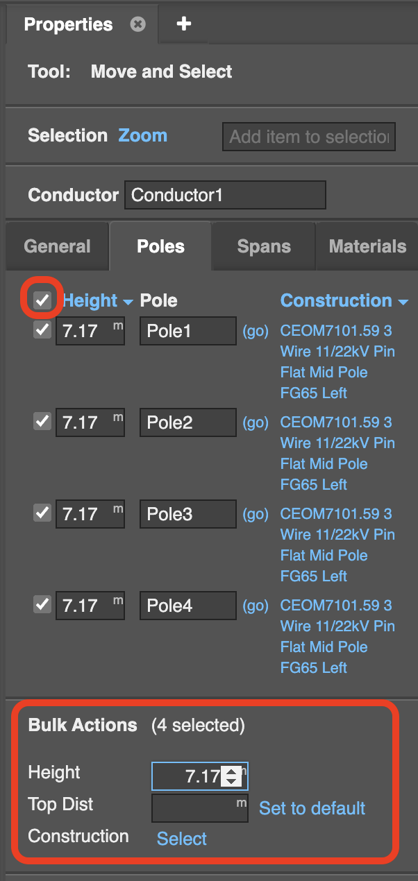
First, make sure the attachment heights of the constructions across the poles are correct:
- Select a conductor
- Click the Poles tab in the Properties panel in the sidebar
- Enter in a Top distance or Height for each attachment
If all the values should be set the same, tick the top checkbox to select and change all values at once:
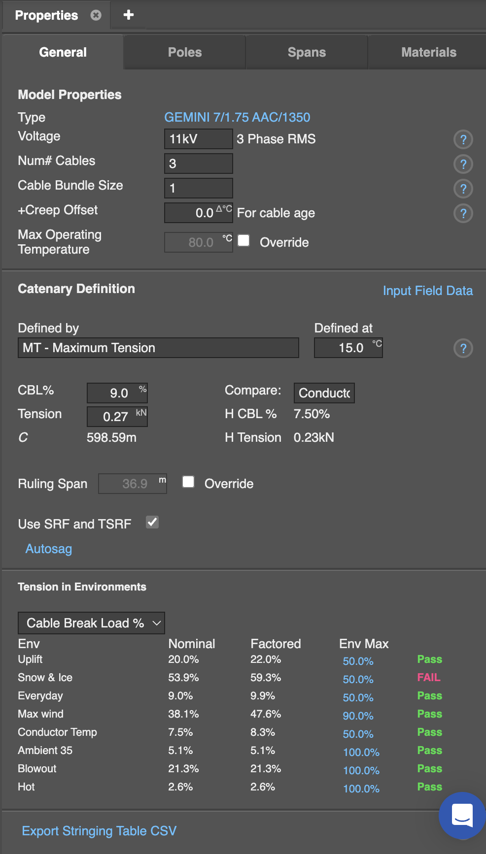
After adjusting the attachment heights of the cross-arms we now focus on the properties of the cable.
- Select a conductor
- Click the General tab in the Properties panel in the sidebar. You may need to resize the panel wider to see all available options.
- Adjust the model properties as necessary
- Define the catenary definition - we will be using maximum tension:
- Maximum Tension: The tension will be such that the maximum tension across all cables at all attachment points does not exceed this value
- Horizontal Tension: The horizontal component of the tension will be set to this value. This is a constant along the entire cable, given the assumptions that tensions equalize.
- The ratio of Sag to ruling span: The tension will be such that the conductor sag is equal to a percentage of the span length. This sag percentage will be maintained as the span length is modified. To give meaningful results when there are uneven spans, the span length used to define the sag is the ruling span
- Separate constrains per cable: The cables are locked to a given length. A starting tension must also be specified so that the conductors may be considered to be strained at the locked length. The length may then extend slightly due to further strain under increased load.
As you change the catenary definition different fields are provided to enter values such as CBL%, Tension, Sag%, Constraint, Length.
Deriving cable tension
In this example we will derive the tension of the cable from the measured sag. To do this we will place a survey conductor point underneath a span on the circuit, and snap the cable sag to it.
Select the Survey tool from the toolbar, and select Conductor as the Type on the Properties tab on the sidebar, and set its height:
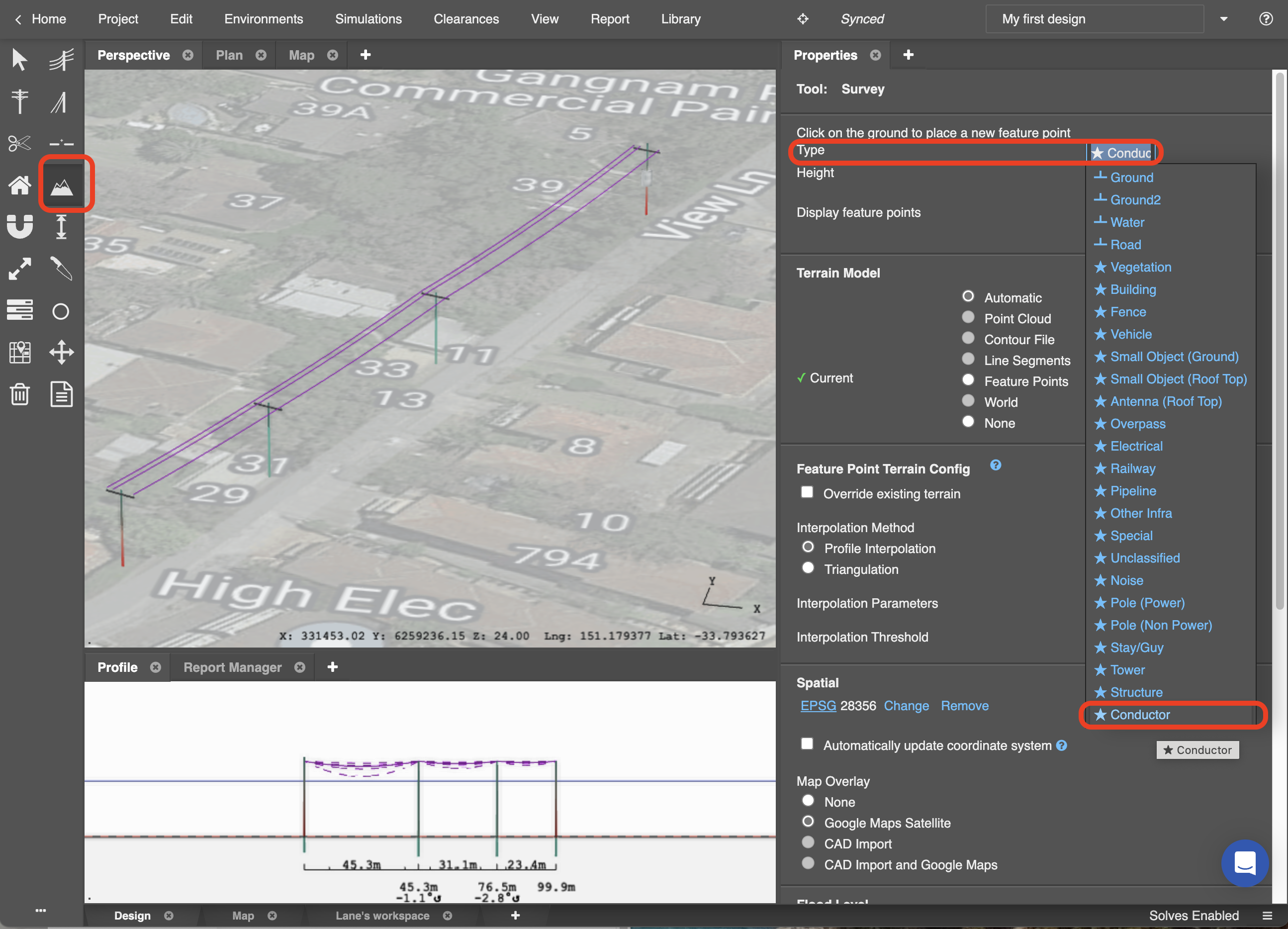
Place the conductor survey point down underneath a span. For greater accuracy, do this in the Profile view in the lower part of the screen:
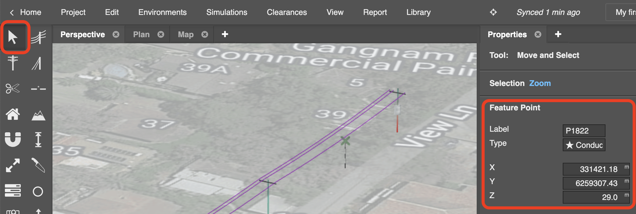
Switch to the Select tool on the toolbar, select the newly-placed conductor survey point, and modify the x, y, and z values in the Properties panel, if required:
Select the Snap tool on the toolbar.
Click the conductor section, select Cable sag under Snapping options in the Properties panel in the sidebar, and then click the placed survey point to snap the cable sag down to it:
We have now modelled our existing line. This includes the poles, conductors and characteristics. Next we will model a new extension using stays, analytic tools and more.