Measuring Blowout distance

Written by Cody Yakimoff
Updated at August 7th, 2023
Contact Us
If you still have questions or prefer to get help directly from an agent, please submit a request.
We’ll get back to you as soon as possible.
- Getting started
- Fundamentals
- Recommended devices & supported browsers
- Creating an account & logging in
- Setting up your organization account & users
- First-time setup
- The Home screen & your first Project
- Using the Project screen & workspaces
- Project design settings
- Moving and selecting objects
- Positioning and orienting the camera in 2D and 3D views
- Keyboard shortcuts
- Review & export Project settings as a template
- Collaborating on designs with other users
- Connecting external cloud data sources
- Create a cross section of your model in the Profile view
- Importing a model/template file
- Set a project's units of measurement to Metric or US
- Improving display performance
- Tutorial: Your first design
- Network design & analysis
- Project setup
- Working with the coordinate system
- Setting up and using Environments
- Adding a map overlay to your design
- Create a cross section of your model in the Profile view
- Viewing & using datasets in your network model
- View options: asset color coding, displayed visuals, and point cloud display
- Video: Scoping in Neara Designer
- Video: Rapid project scoping for overhead powerline design
- Video: View and export profiles of overhead line models
- M(z,cat) Gust Wind Speed Multiplier
- Span Reduction Factor SRF and Tension Section Reduction Factor TSRF
- Importing a model/template file
- Set a project's units of measurement to Metric or US
- Improving display performance
- Issues importing DXF files
- Using Libraries
- Using and updating libraries
- The Constructions (Assemblies) library
- The Constructions and Components Library
- Example Constructions and Components
- No cable constructions
- Creep Modelling
- Video: Editing Pole Top Constructions
- Video: Editing Pole Top Construction components
- Pole Library: Derive Modulus of Rupture From Tipload
- How do I create a new construction?
- How do I model a T-junction construction?
- How do I change from one pole top construction to another?
- How do I create a new component?
- Using Environments
- Overhead
- Poles
- Placing poles
- Adding a stay/guy wire to a pole
- Using precision relative placement to place poles relative to other objects
- Extracting & fitting poles to LiDAR and working with imagery tiles
- Using the Snap tool to fine tune the fit of poles & conductors to LiDAR data
- Analysing the impact of single & multiple stays on a pole
- Viewing detailed tip load results in the Tip Load panel
- Classify spans and poles to be existing, new, replaced, re-tensioned, or removed
- Video: Using the precision placement tool
- Video: Editing Pole Top Constructions
- Video: Editing Pole Top Construction components
- Overview Limit State Table
- Resultant Forces Graph
- Detailed Forces table
- Creating mid-span Poles
- Setting a manual or calculated custom Pole Strength
- Specifying Pole Lean
- Pole stiffness multiplier widget
- Conductors
- Using the Conductor tool to place & configure conductor spans
- Viewing & modifying conductor span properties
- Setting conductor properties
- Splitting conductors
- Joining conductors
- Creating and attaching Mid-cable Objects to spans
- Using the Snap tool to fine tune the fit of poles & conductors to LiDAR data
- Measuring Blowout distance
- Measuring conductor clearances
- Measuring ground clearance
- Individual cable tensions on a conductor span
- Creep Modelling
- Classify spans and poles to be existing, new, replaced, re-tensioned, or removed
- Video: Using the NESC Ground Clearance tool
- Video: Creating Multiple Conductor Groups
- Video: View and export profiles of overhead line models
- Set up derating strength factors on conductors, poles, and components
- Creating mid-span Poles
- How do I specify a precise span length?
- How do I extend an existing conductor?
- How do I insert a pole into an existing conductor span?
- How do I find the blowout of a span?
- Defining Bimetallic Conductors
- Analysing Bimetallic Cables
- Stays / Guys
- Crossarms
- Overview of crossarm parameters
- Crossarm parameter: Second Moment of Area
- Crossarm parameter: Torsion Constant
- Crossarm parameter: Section Modulus
- Crossarm parameter: Material
- Crossarm parameters: Length, width, depth
- Crossarm parameter: Mass
- Crossarm parameter: Maximum Bending Moment
- Crossarm parameter: Max Bending Moment vs Horizontal/Vertical
- Crossarm parameter: Material Strength
- How do I create a double cross-arm?
- Obstructions and structures
- Structural analysis
- Wind analysis
- Finite Element Analysis (FEA)
- Analysing the impact of single & multiple stays on a pole
- Design Setting - Removed Status Stops Loads From Being Applied
- Set up Simulations for use with FEA
- Set up derating strength factors on conductors, poles, and components
- FEA: Unstressed Lengths
- FEA: Deflection and Rotation Angle
- FEA: Load Source
- FEA: Load Factors
- The FEA simulations pipeline
- Static Analysis
- Analysing the impact of single & multiple stays on a pole
- Viewing detailed tip load results in the Tip Load panel
- Design Setting - Removed Status Stops Loads From Being Applied
- Set up derating strength factors on conductors, poles, and components
- Overview Limit State Table
- Resultant Forces Graph
- Detailed Forces table
- Setting a manual or calculated custom Pole Strength
- Calculations
- Example models from AS7000 HB 331-2012
- Sag Measurement
- General Conductor Properties and calculations
- Blowout Calculation
- Tip Load Calculations
- Stay Calculation
- Sag Tension Calculation
- Pole Plant Calculation
- Span Clearance Calculations
- Catenary Definition
- Torsion Constant
- Neutral Axis
- Moments of Area
- Second Moment of Area
- Section Modulus
- Maximum Bending Moment
- Modulus of Elasticity
- Stress / Strain
- Maximum Bending Stress / Material Strength
- Common Shapes: Second Moment of Area and Torsion Constant
- Underground
- Measuring Clearances
- Working with Terrain
- Working with LiDAR data
- Automatic LiDAR Classification
- Modelling with LiDAR
- Quickstart: Overview of modelling with LiDAR
- Video: Modelling with LiDAR in Neara
- View options: asset color coding, displayed visuals, and point cloud display
- Manage density, view, and sets of LiDAR
- Extracting & fitting poles to LiDAR and working with imagery tiles
- Using the Snap tool to fine tune the fit of poles & conductors to LiDAR data
- Viewing & using datasets in your network model
- Reports and visualizations
- An introduction to Neara Reports
- Creating custom reports
- Managing existing Reports
- Working with tables in Reports
- Using formulas in reports
- Interactive Parameter controls in Reports
- Export data from a Report
- Quick exports with built-in Reports
- Built-in Point Cloud clearance report
- Exploring data-driven panels in the Perspective view
- Vegetation Management
- Formula language reference
- Using formulas in reports
- Logical & Boolean operations
- Mathematical operations
- Constants
- Text operations and formatting
- Units: types and operations
- Lists and Collections
- Engineering operations, calculations, and simulations
- Geometries and Bodies
- Creating Volumes and making Point Cloud selections
- User Interface operations
- Miscellaneous operations
- Example formula: Custom clearance height check
- Collaboration
In order to ensure that conductors have sufficient clearance to the sides as well, the Conductor Clearance tool on the toolbar can be used to see the blowout of the conductors under max wind conditions.
For example, if there are two lines close to each other as shown in the below image, we can see the minimum distance between them in the event of a blowout:
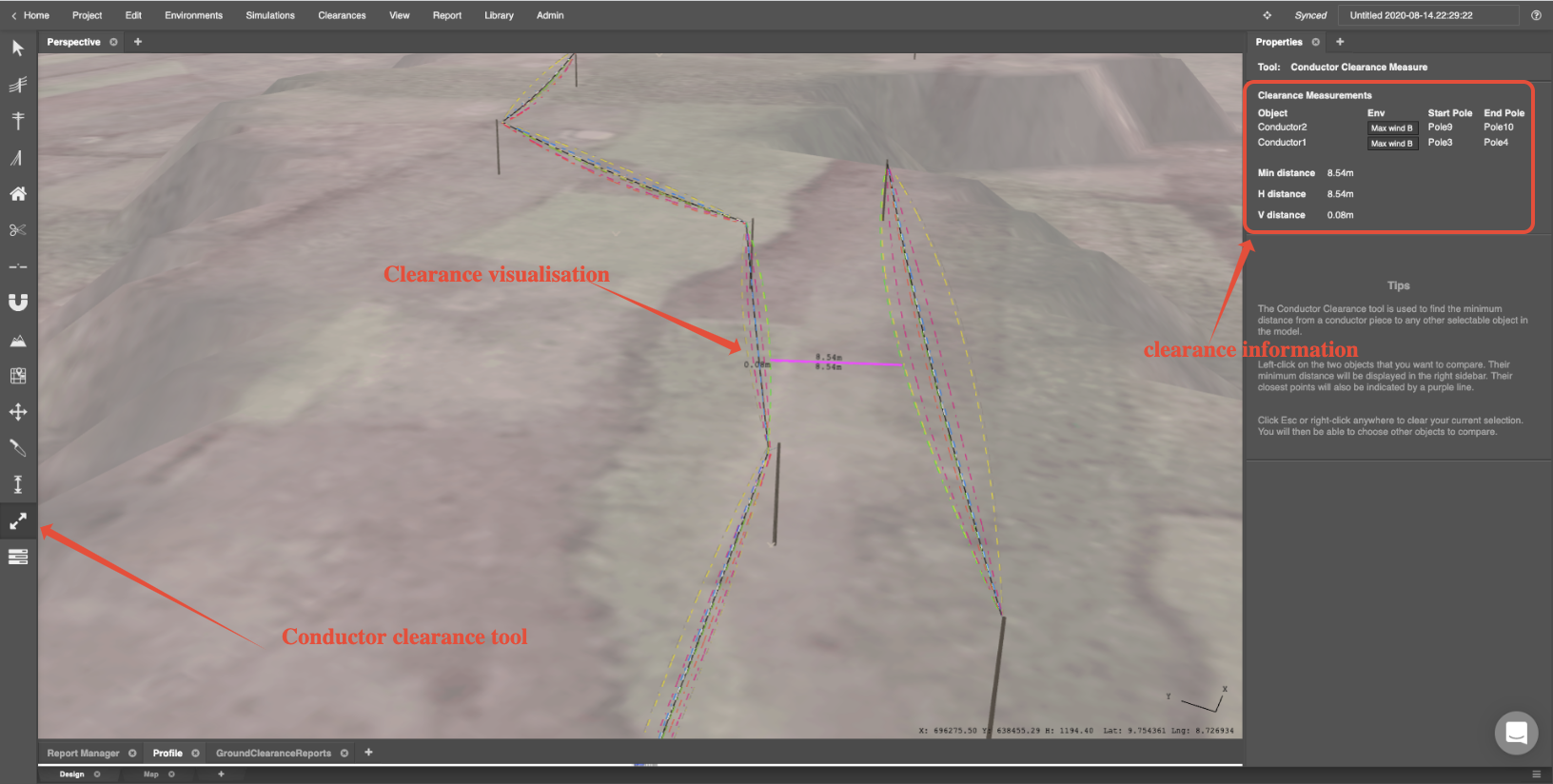
In order to determine this measurement, first click on the conductor clearance tool in the left toolbar as shown.
The blowout (labelled Max wind by default in the Environments field) is shown by the dotted yellow-colored lines on either side of the conductors.
By first clicking the Conductor Clearance tool and then left-clicking the two blowout lines to measure between, a magenta-colored line will appear between the points to visualise the clearance being measured.
The clearance information in the top right provides information on which two conductors the measurement is between as well as the minimal distance between them and the breakdown of horizontal and vertical distances.
Note that the line will always appear where the distance is minimized between the two spans, rather than where on the span you click.