Measuring ground clearance

Written by Cody Yakimoff
Updated at August 14th, 2023
Table of Contents
Measuring the clearance between conductors and other objects
To measure the clearance between a conductor and other objects such as buildings or vegetation, or to another conductor, use the Clearance Measure tool instead. This tool also enables fine tuning on the specific environment chosen, conductor in a span used and the start and end points.
Measuring the clearance between a conductor and the ground
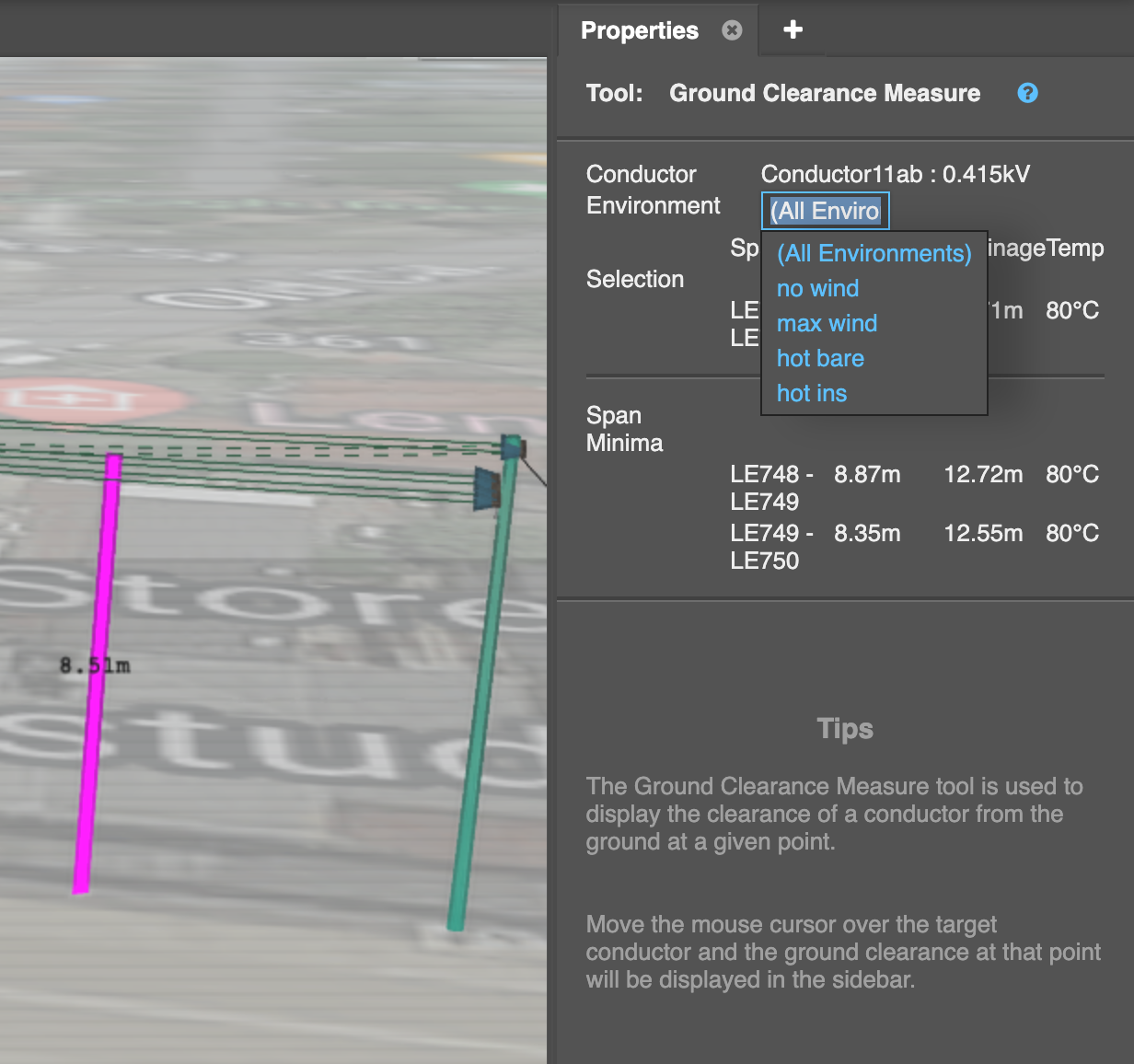
Select the Ground Clearance Measure tool on the toolbar and hover over or left-click on a conductor.
Neara will display the worst-case ground clearance of a span as a magenta line in both Perspective view and Profile view (shown in the lower-half of this workspace):
In the Properties panel in the sidebar, you can modify the environment to see clearances under different conditions, with the cable sag shown:
Note: The ground line measured to is based on the terrain model chosen in the survey tool and more detail can be found here: Creating a ground-terrain profile
Set up different ground clearance heights
One of the most important aspects of any design is ensuring that conductors do not sag below a certain ground clearance height. If it sags too low either its tension must be increased or its supporting poles moved closer together.
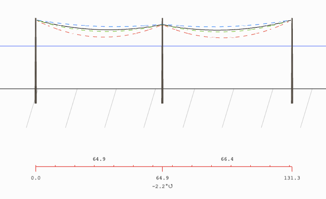
Neara makes it easy to visualize this in the Profile view. The blue line parallel to the ground represents the clearance level, and the dotted lines represent the cable span under different environmental conditions:
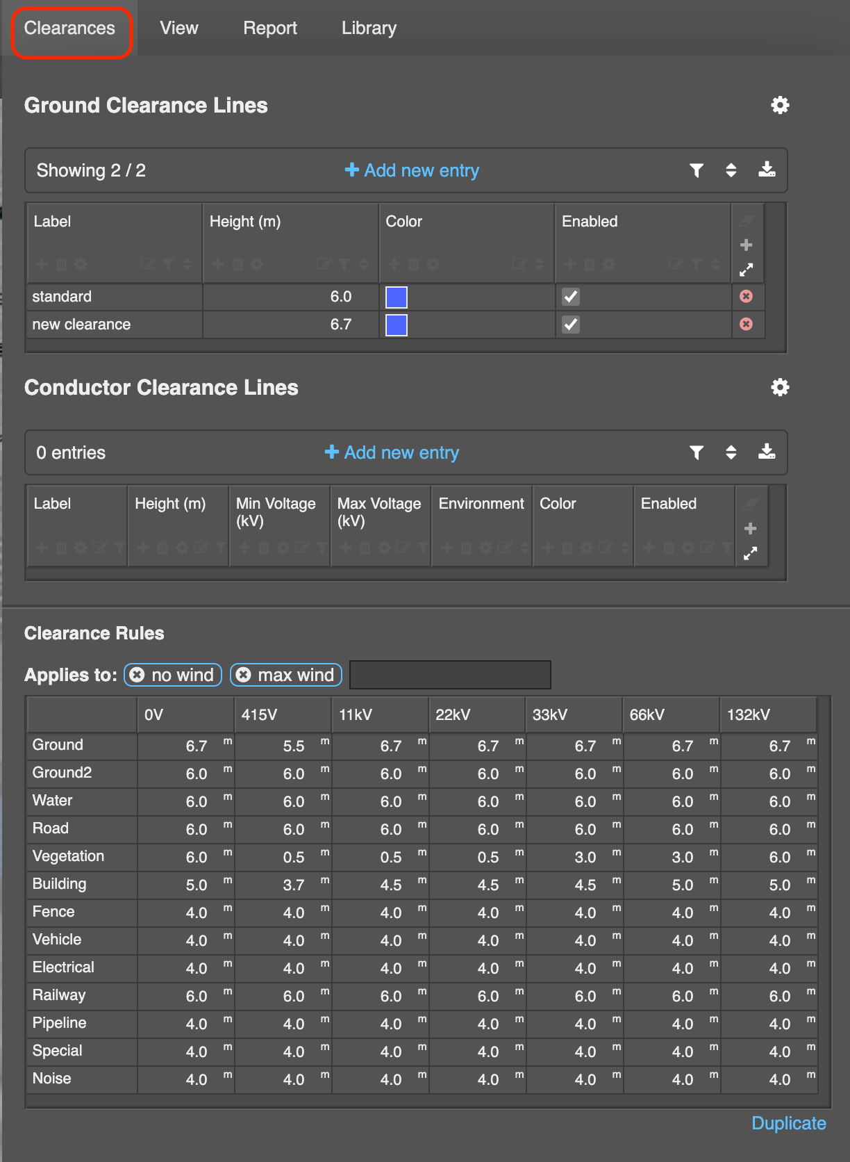
Ground clearance lines and Clearance Rules can be added and modified in the project under the Clearances menu: