Creating a ground / terrain profile using the Survey tool
Learn how to create an accurate ground/terrain profile using Survey Tool features.

Written by Cody Yakimoff
Updated at August 7th, 2023
Table of Contents
Options to create a ground profile
There are multiple ways to create a ground profile in Neara:
- Import a survey file
- Import a DXF file
- Import LiDAR data
- Create a ground / terrain profile manually with the Survey tool (this article)
The Survey tool allows you to place a sequence of feature points with x,y, and z (elevation) values. The ground elevation is linearly interpolated between consecutive height points in the sequence.
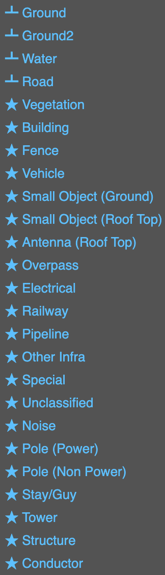
You can place a variety of feature points with this tool - however only the Ground, Water, and Road types are used to create a ground profile:
Import an overlay image
Before placing a survey feature point, it is useful to import an overlay image from a DXF file or Google Maps®.
DXF overlay
Import a DXF file by selecting Project menu > Import from DXF and select Overlay after you have select a DXF file from your device.
Google Maps overlay
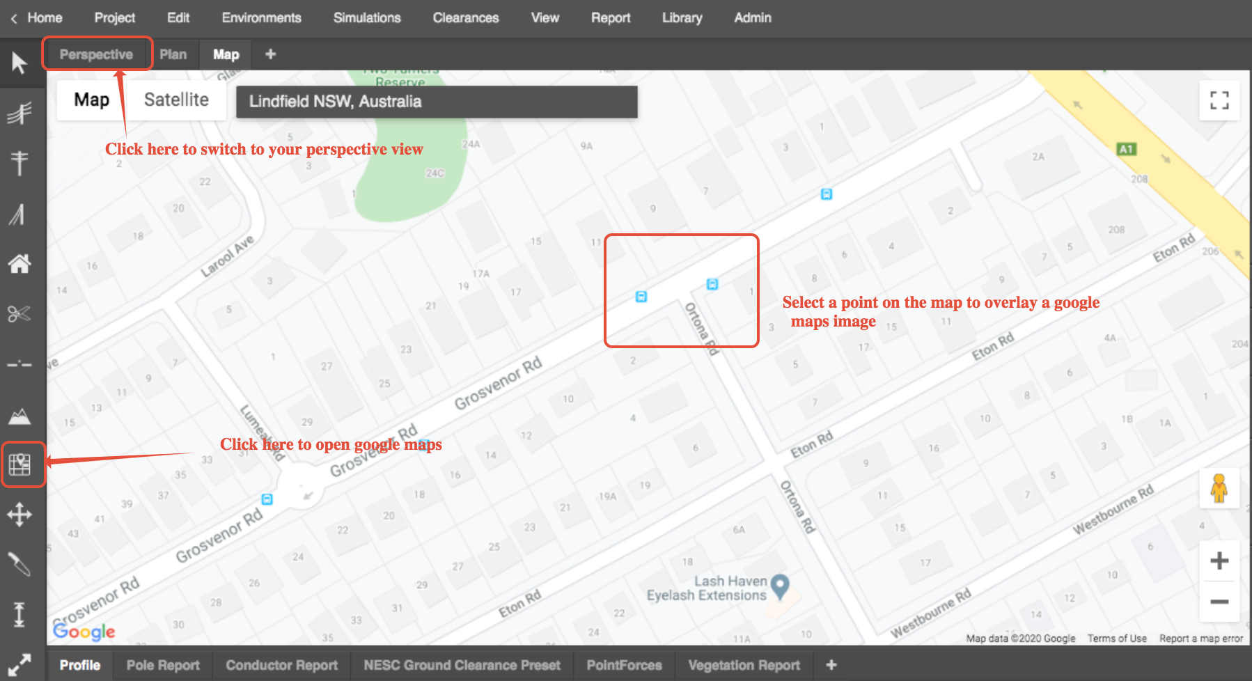
You can also import a Google Maps overlay by selecting the Map tool on the toolbar, and then search for your design area using the Search bar at the top of the map area.
Click on a location on the map to load the overlay:
Next, enter an EPSG code to initiate the coordinate system. This can be done by selecting Edit in the Properties panel in the sidebar:
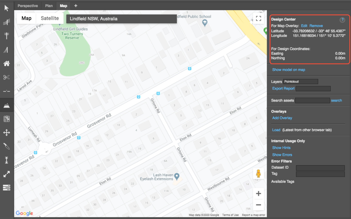
Entering an EPSG code for your area in the popup that appears - we will use 28356 for NSW. We will also select Derive Design Coord Centre From Lat/Lng as we do not have a coordinate centre at the moment, and then click the Apply and option to give the design a coordinate system.
We use the other option when we have a coordinate centre if we have already imported a survey file with eastings and northings, or if we have input an object into the design area with an easting and northing.
Switch back to the Perspective view to view the map overlay.
Create a ground profile
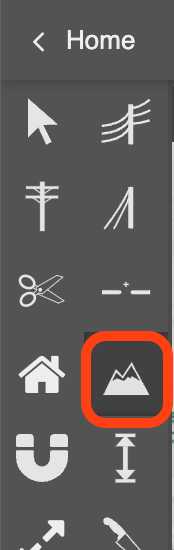
Select the Survey tool from the toolbar:
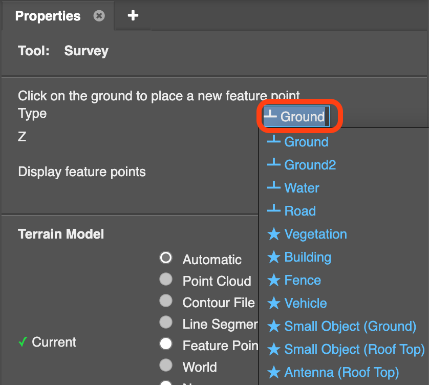
In the Survey tool Properties panel that appears in the sidebar, select one of the ground profile feature points: Ground, Water, or Road by clicking in the type box to reveal the drop-down options:
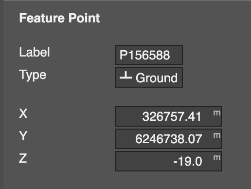
Place a couple of feature points by clicking in different locations in the Perspective view. Specify the x and y coordinates and the z height of each feature point in the Properties panel:
Interpolating terrain points
You can have Neara interpolate between two terrain points if they are far away and you assume a continuous profile between the two points.
Feature Point Terrain configuration
The following options are available when interpolating terrain points:
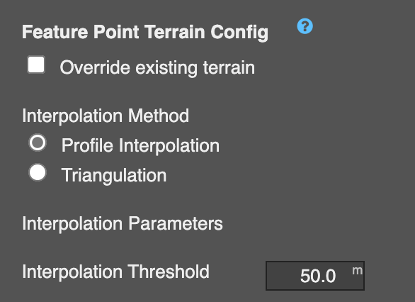
Override existing terrain
Determines whether the feature point terrain should override any other existing terrain in areas where there are feature points
Interpolation Methods
The different methods of producing terrain from the given feature points. Each interpolation method has its own interpolation parameters.
Profile interpolation
The height of the terrain at any point is interpolated by using the weighted average of the two nearest feature points on either side of the terrain point.
Parameters:
- Interpolation Threshold: Terrain points further than this distance from a feature point will be considered too far to have their height interpolated by feature points.
Triangulation
The height of the terrain is computed by creating a triangular TIN mesh from the provided feature points. Regions outside of the triangular mesh can have their heights interpolated from the edges of the mesh.
Parameters:
- Interpolation Threshold: Terrain points further than this distance from a feature point will be considered too far to have their height interpolated by feature points.
- Clustering Threshold: Distance for feature points to belong to the same triangular mesh.