How to model a Side-Walk Stay?
Written by Cody Yakimoff
Updated at November 30th, 2022
Contact Us
If you still have questions or prefer to get help directly from an agent, please submit a request.
We’ll get back to you as soon as possible.
- Getting started
- Fundamentals
- Recommended devices & supported browsers
- Creating an account & logging in
- Setting up your organization account & users
- First-time setup
- The Home screen & your first Project
- Using the Project screen & workspaces
- Project design settings
- Moving and selecting objects
- Positioning and orienting the camera in 2D and 3D views
- Keyboard shortcuts
- Review & export Project settings as a template
- Collaborating on designs with other users
- Connecting external cloud data sources
- Create a cross section of your model in the Profile view
- Importing a model/template file
- Set a project's units of measurement to Metric or US
- Improving display performance
- Tutorial: Your first design
- Network design & analysis
- Project setup
- Working with the coordinate system
- Setting up and using Environments
- Adding a map overlay to your design
- Create a cross section of your model in the Profile view
- Viewing & using datasets in your network model
- View options: asset color coding, displayed visuals, and point cloud display
- Video: Scoping in Neara Designer
- Video: Rapid project scoping for overhead powerline design
- Video: View and export profiles of overhead line models
- M(z,cat) Gust Wind Speed Multiplier
- Span Reduction Factor SRF and Tension Section Reduction Factor TSRF
- Importing a model/template file
- Set a project's units of measurement to Metric or US
- Improving display performance
- Issues importing DXF files
- Using Libraries
- Using and updating libraries
- The Constructions (Assemblies) library
- The Constructions and Components Library
- Example Constructions and Components
- No cable constructions
- Creep Modelling
- Video: Editing Pole Top Constructions
- Video: Editing Pole Top Construction components
- Pole Library: Derive Modulus of Rupture From Tipload
- How do I create a new construction?
- How do I model a T-junction construction?
- How do I change from one pole top construction to another?
- How do I create a new component?
- Using Environments
- Overhead
- Poles
- Placing poles
- Adding a stay/guy wire to a pole
- Using precision relative placement to place poles relative to other objects
- Extracting & fitting poles to LiDAR and working with imagery tiles
- Using the Snap tool to fine tune the fit of poles & conductors to LiDAR data
- Analysing the impact of single & multiple stays on a pole
- Viewing detailed tip load results in the Tip Load panel
- Classify spans and poles to be existing, new, replaced, re-tensioned, or removed
- Video: Using the precision placement tool
- Video: Editing Pole Top Constructions
- Video: Editing Pole Top Construction components
- Overview Limit State Table
- Resultant Forces Graph
- Detailed Forces table
- Creating mid-span Poles
- Setting a manual or calculated custom Pole Strength
- Specifying Pole Lean
- Pole stiffness multiplier widget
- Conductors
- Using the Conductor tool to place & configure conductor spans
- Viewing & modifying conductor span properties
- Setting conductor properties
- Splitting conductors
- Joining conductors
- Creating and attaching Mid-cable Objects to spans
- Using the Snap tool to fine tune the fit of poles & conductors to LiDAR data
- Measuring Blowout distance
- Measuring conductor clearances
- Measuring ground clearance
- Individual cable tensions on a conductor span
- Creep Modelling
- Classify spans and poles to be existing, new, replaced, re-tensioned, or removed
- Video: Using the NESC Ground Clearance tool
- Video: Creating Multiple Conductor Groups
- Video: View and export profiles of overhead line models
- Set up derating strength factors on conductors, poles, and components
- Creating mid-span Poles
- How do I specify a precise span length?
- How do I extend an existing conductor?
- How do I insert a pole into an existing conductor span?
- How do I find the blowout of a span?
- Defining Bimetallic Conductors
- Analysing Bimetallic Cables
- Stays / Guys
- Crossarms
- Overview of crossarm parameters
- Crossarm parameter: Second Moment of Area
- Crossarm parameter: Torsion Constant
- Crossarm parameter: Section Modulus
- Crossarm parameter: Material
- Crossarm parameters: Length, width, depth
- Crossarm parameter: Mass
- Crossarm parameter: Maximum Bending Moment
- Crossarm parameter: Max Bending Moment vs Horizontal/Vertical
- Crossarm parameter: Material Strength
- How do I create a double cross-arm?
- Obstructions and structures
- Structural analysis
- Wind analysis
- Finite Element Analysis (FEA)
- Analysing the impact of single & multiple stays on a pole
- Design Setting - Removed Status Stops Loads From Being Applied
- Set up Simulations for use with FEA
- Set up derating strength factors on conductors, poles, and components
- FEA: Unstressed Lengths
- FEA: Deflection and Rotation Angle
- FEA: Load Source
- FEA: Load Factors
- The FEA simulations pipeline
- Static Analysis
- Analysing the impact of single & multiple stays on a pole
- Viewing detailed tip load results in the Tip Load panel
- Design Setting - Removed Status Stops Loads From Being Applied
- Set up derating strength factors on conductors, poles, and components
- Overview Limit State Table
- Resultant Forces Graph
- Detailed Forces table
- Setting a manual or calculated custom Pole Strength
- Calculations
- Example models from AS7000 HB 331-2012
- Sag Measurement
- General Conductor Properties and calculations
- Blowout Calculation
- Tip Load Calculations
- Stay Calculation
- Sag Tension Calculation
- Pole Plant Calculation
- Span Clearance Calculations
- Catenary Definition
- Torsion Constant
- Neutral Axis
- Moments of Area
- Second Moment of Area
- Section Modulus
- Maximum Bending Moment
- Modulus of Elasticity
- Stress / Strain
- Maximum Bending Stress / Material Strength
- Common Shapes: Second Moment of Area and Torsion Constant
- Underground
- Measuring Clearances
- Working with Terrain
- Working with LiDAR data
- Automatic LiDAR Classification
- Modelling with LiDAR
- Quickstart: Overview of modelling with LiDAR
- Video: Modelling with LiDAR in Neara
- View options: asset color coding, displayed visuals, and point cloud display
- Manage density, view, and sets of LiDAR
- Extracting & fitting poles to LiDAR and working with imagery tiles
- Using the Snap tool to fine tune the fit of poles & conductors to LiDAR data
- Viewing & using datasets in your network model
- Reports and visualizations
- An introduction to Neara Reports
- Creating custom reports
- Managing existing Reports
- Working with tables in Reports
- Using formulas in reports
- Interactive Parameter controls in Reports
- Export data from a Report
- Quick exports with built-in Reports
- Built-in Point Cloud clearance report
- Exploring data-driven panels in the Perspective view
- Vegetation Management
- Formula language reference
- Using formulas in reports
- Logical & Boolean operations
- Mathematical operations
- Constants
- Text operations and formatting
- Units: types and operations
- Lists and Collections
- Engineering operations, calculations, and simulations
- Geometries and Bodies
- Creating Volumes and making Point Cloud selections
- User Interface operations
- Miscellaneous operations
- Example formula: Custom clearance height check
- Collaboration
Table of Contents
To model a side-walk stay you will need to follow these steps:
Adding a Stay and Opening the Stay-Pole Construction Library
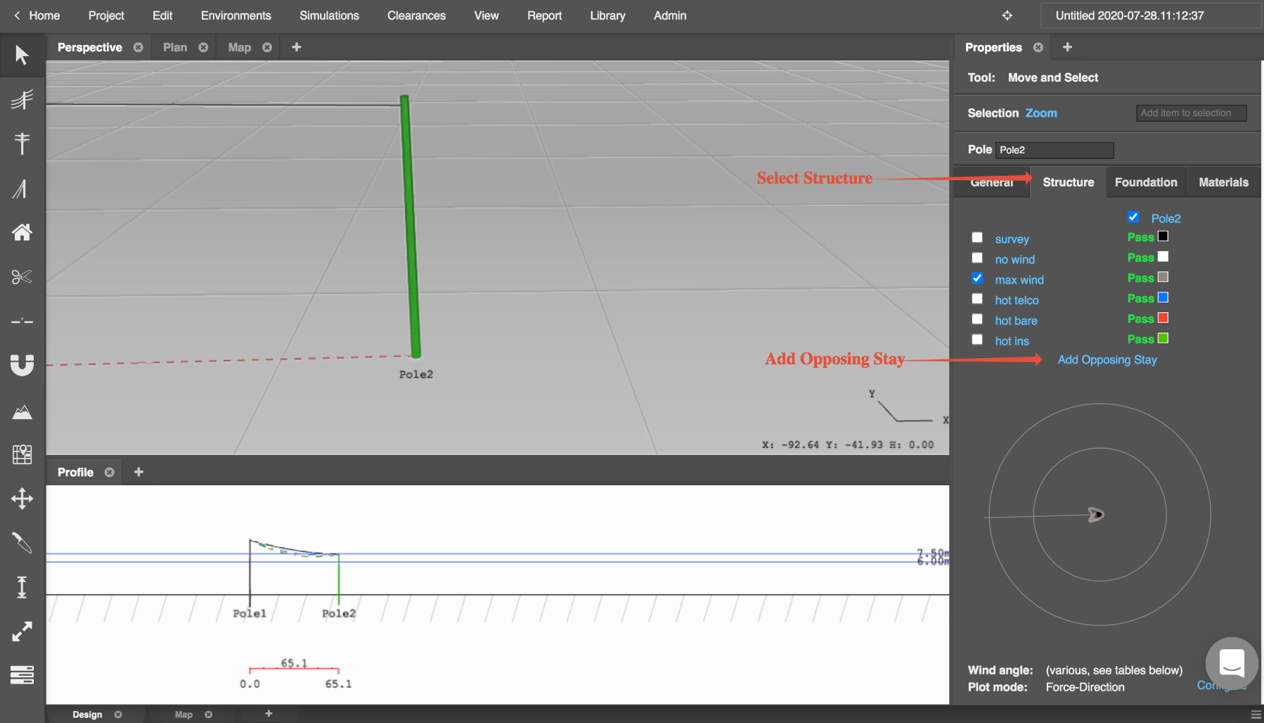
- Select the pole you would like to attach your stay to and navigate to the properties tab
- Select "Structure" in the properties tab
- Select “Add Opposing Stay”
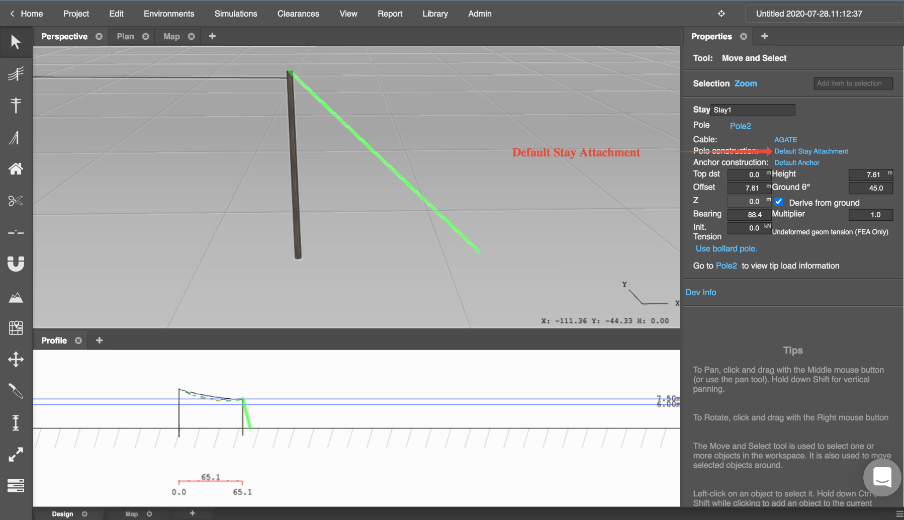
- Select the Stay to populate the properties tab with the stay properties
- Select "Default Stay Attachment" to open up the stay pole construction library
Creating and Using your Side-Walk Stay
Before you create your side-walk stay make sure to create the relevant components in the component library. You will need a cross-arm and a brace.
- Select “Default Stay Attachment”
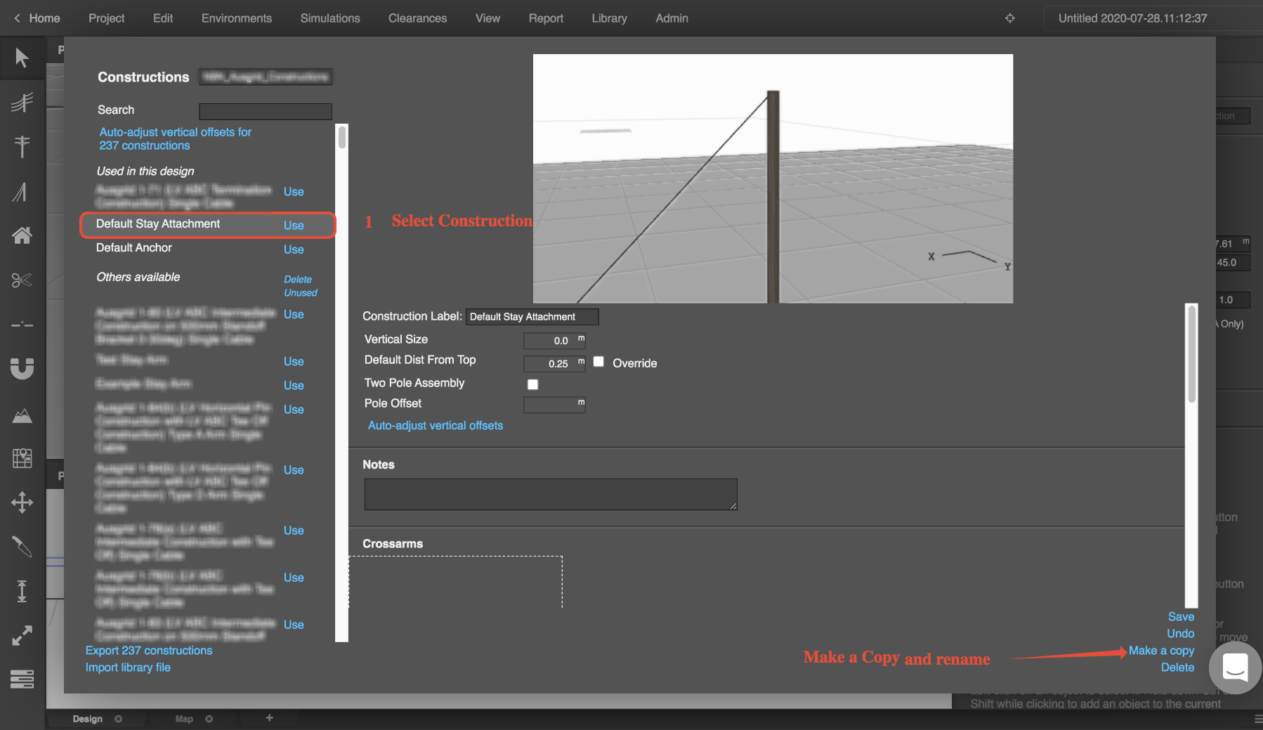
- Make a copy of the construction and name it accordingly
- Select "Add New Crossarm" and attach a left or right brace
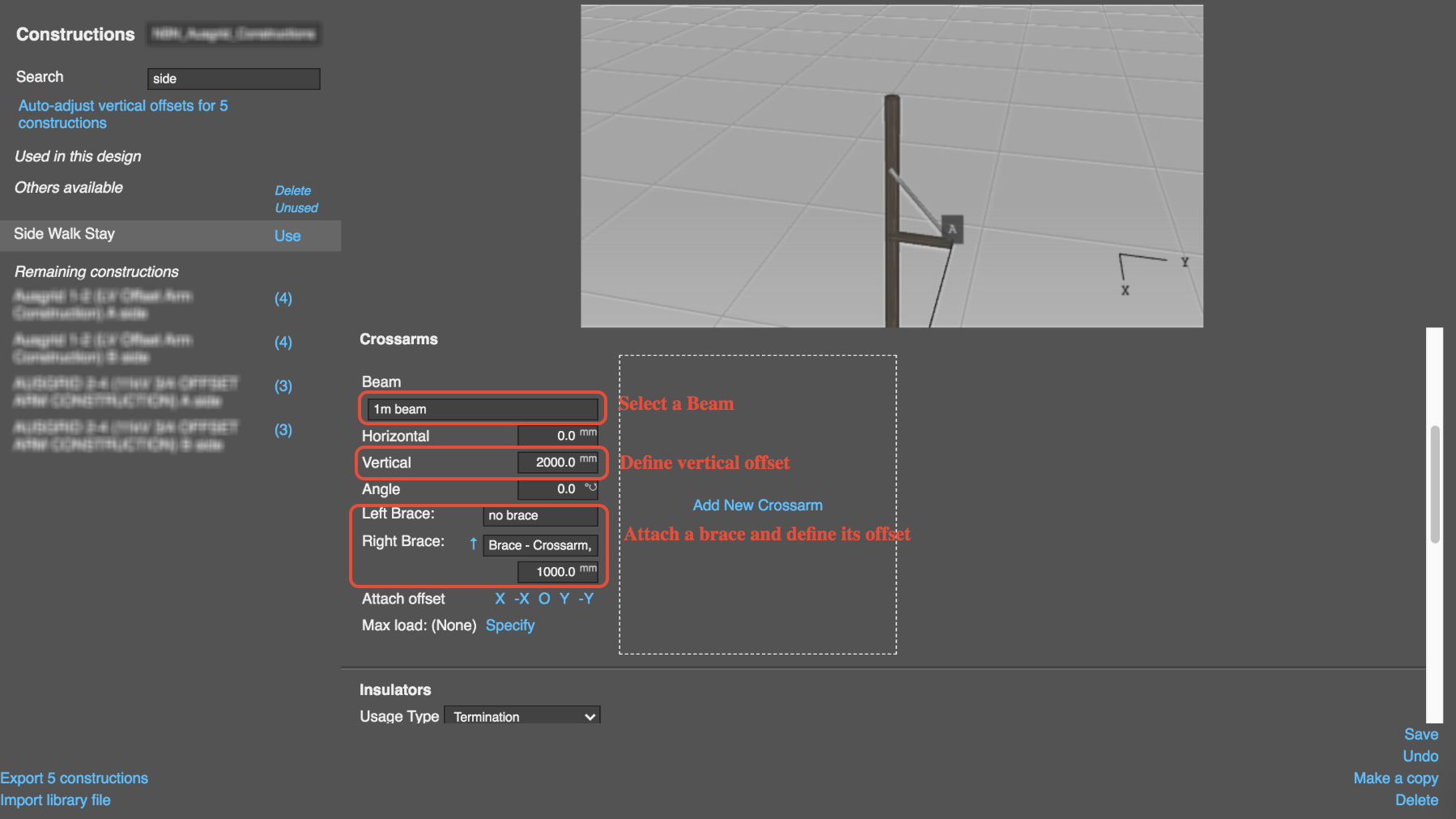
- Select the Blue Arrow next to your brace selection to flip the positioning vertically
- Set the Vertical offset to situate it from a fixed distance from the top of the pole
Note
you can also select the sides in which you want the cross-arm attached to by select X -X 0 Y -Y.
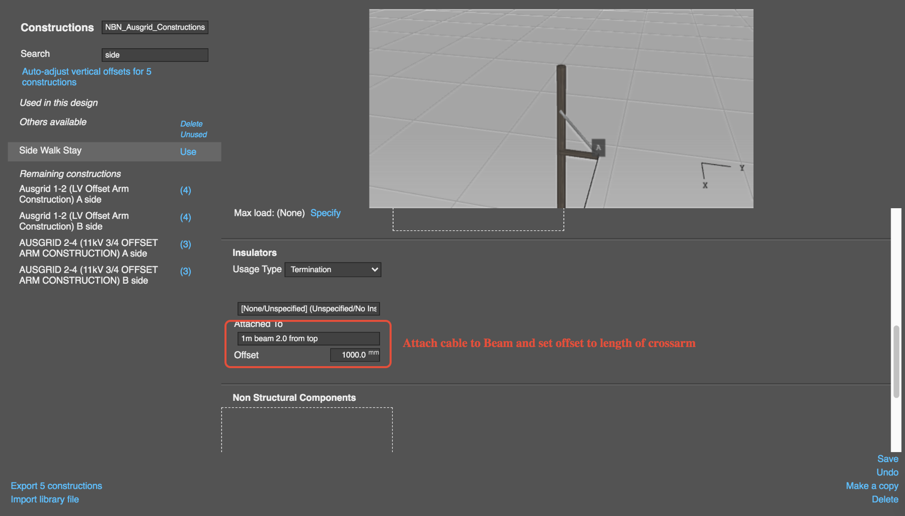
- Set the insulator attachment offset so that the stay cable is attached to the end of the cross arm
- Select "Save" and then click “Use”
- Select the stay and set the offset to 0m to make it vertical