Quickstart: Overview of modelling with LiDAR

Written by Cody Yakimoff
Updated at January 4th, 2023
Table of Contents
Neara automatically generates a 3D vector model from a classified point cloud dataset, and intelligently reclassifies LiDAR based on heuristics and relationship to the model.
This article provides a quick overview of how to use Neara to model a network from LiDAR data. For more detailed guides and information, browse or search the other articles in this section.
Video walkthrough
Step-by-step
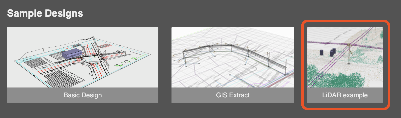
Open the example
After logging in to Neara, on the Home screen click the LiDAR example tile in the Sample Designs section:
Changing point size and coloring
Once the model has loaded, you can change the point size and point coloring using the View menu:
Using the Datasets tool
The Datasets tool on the toolbar is used to modify and configure the LiDAR data imported into the model:
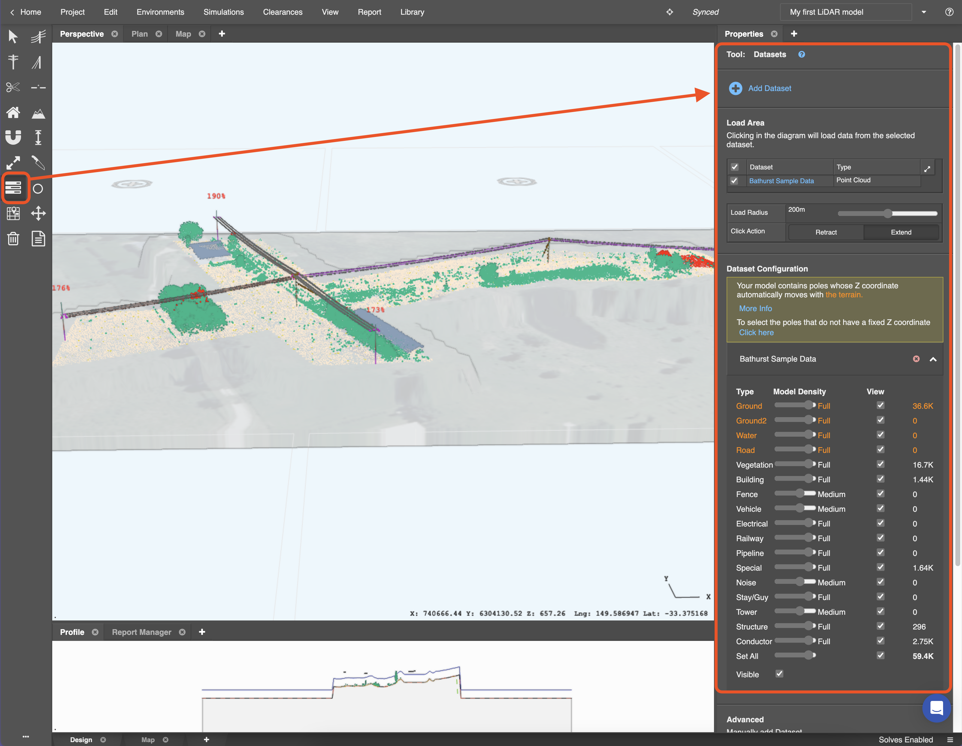
Under the Dataset configuration section of the Datasets panel in the sidebar you'll see a list of all point Types in each LiDAR dataset that has been imported.
For each dataset you can define the:
-
Model density: define the density of each classification: the number of points you want to render
- If your device is running slow, or some classifications are not needed, you can reduce their density - or turn them off completely by moving the slider to its lowest setting.
-
View: toggle a classification's View checkbox if you want to make the LiDAR point cloud viewable in the design or not
- It is typically good practice to turn the View off for Ground points to avoid making the display too busy, and to make it easier to see the map overlay.
Poles & conductors
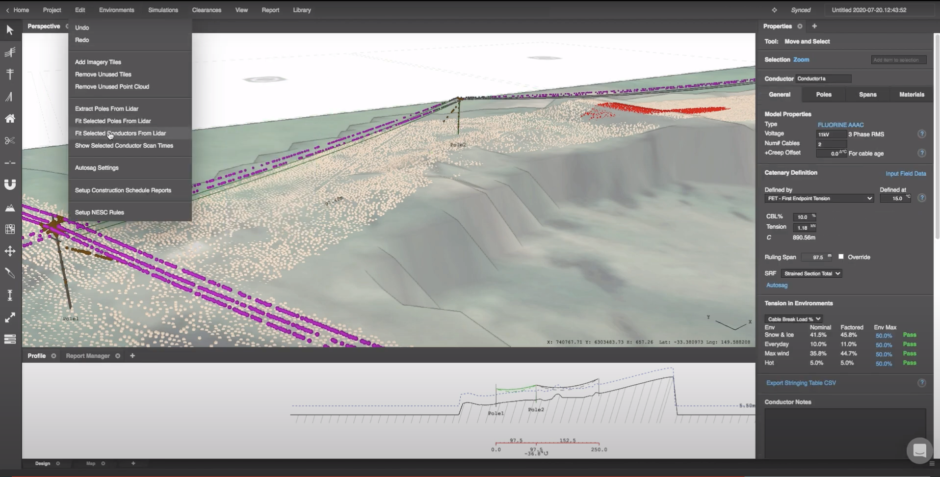
Poles, stays and crossarms are shown as brown in the LiDAR, while conductors are purple. Other special elements are shown in yellow and buildings are in blue.
By clicking on a LiDAR point, the classification can be seen in the properties tab
Poles can be instantly placed wherever they are shown on the LiDAR data by clicking Edit menu > Extract poles from LiDAR. Their placement can then by fine tuned with the use of the Snap tool on the toolbar (learn more).
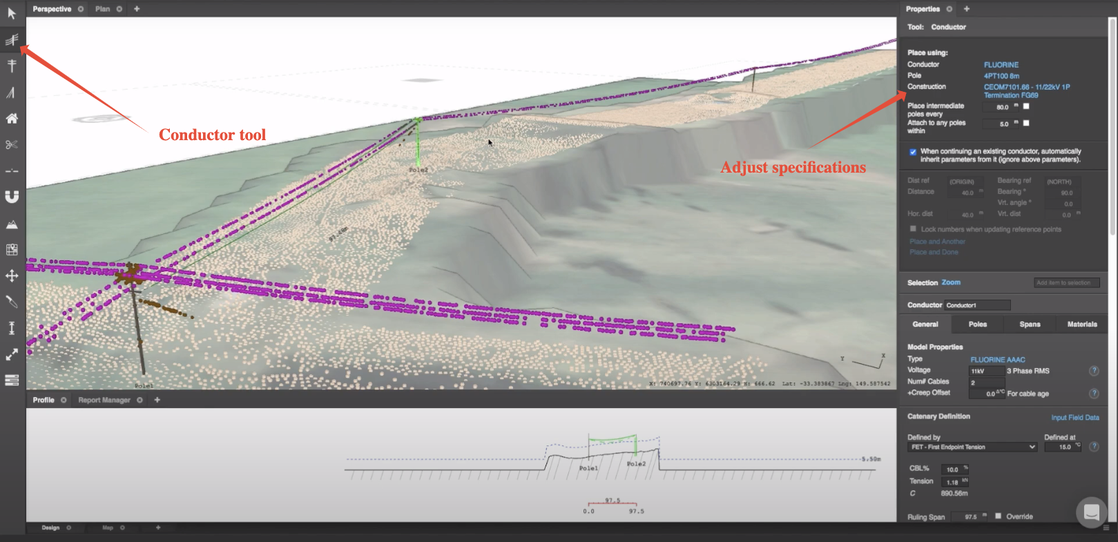
To place conductors, click the Conductor tool on the toolbar and ensure that the specifications on the right of the screen are correct.
Here, the pole type and conductor type/construction can be modified. Once this has been done, left click on the poles that you would like to create spans across and right click to exit the tool once you have finished creating your circuit:
If poles need to be individually adjusted, this is done by clicking on them with the arrow tool and adjusting the specifications on the right to change its constructions.
When a cable fits the LiDAR points, they will turn from purple to grey. There are two ways to ensure this occurs:
- Select the conductor and click on the 'fit selected conductors from LiDAR' tool found in the edit menu item:
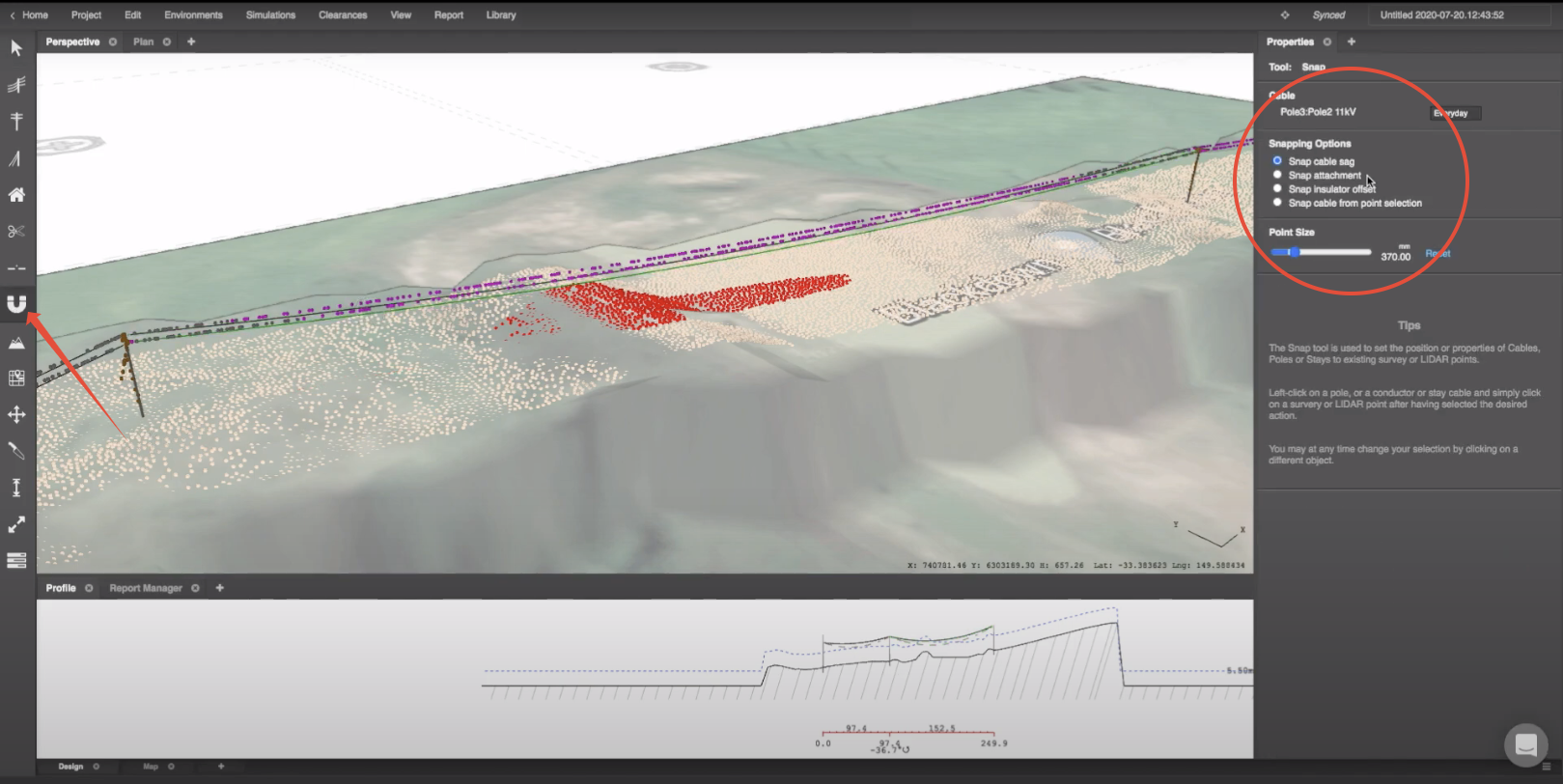
- Select the snap tool to fine tune the attachment point, cable sag and insulator offset of a span. In order to do this, select the cables you wish to fine tune and choose a setting on the right, then click on the desired LiDAR points to snap to: