Model Terrain Override for Poles

Written by Mackenzie Alexander
Updated at September 6th, 2023
Table of Contents
When a Pole is selected with the Move and Select tool on the toolbar, its coordinates are displayed in the Properties Panel.
There are four coordinates to each pole: X, Y, Z and G – with Z and G relating to the model terrain.
By default, the Z value is used to specify the pole base location as this is the same as the Z location of the model terrain at that given point.
However, it is possible to override this using the G value to make the pole use a point higher or lower than the model terrain with the following combination of Z and G values:
- If neither is specified, then
G = model terrain,Z = model terrain - sink depth(sink depth is a primary value) - If
Gis specified,Z = G - sink depth(sink depth is a primary value) - If
Zis specified,G = model terrain,sink depth = G - Z(sink depth is derived) - If
GandZare specified, thensink depth = G - Z(sink depth is derived)
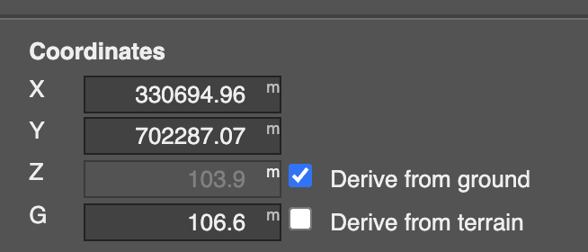
In this case, “specified” means that the checkbox is unticked and the value is manually entered, rather than derived from the ground or terrain
Perspective View visualisation
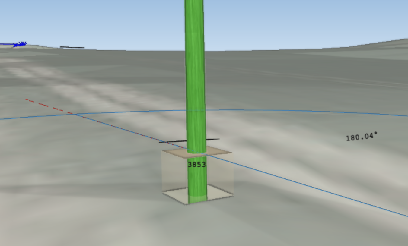
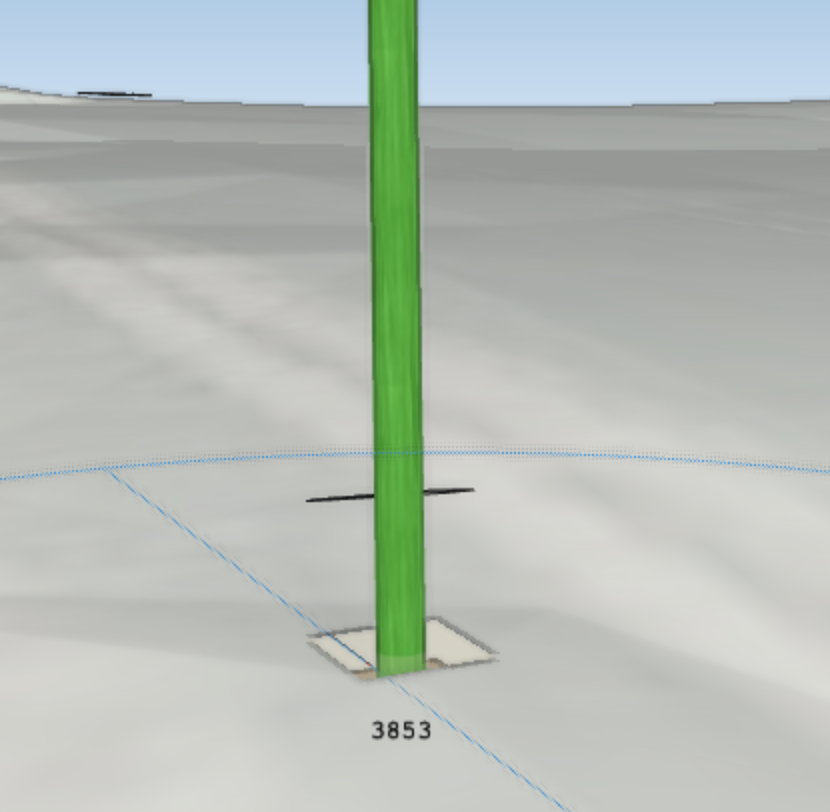
When a G coordinate value is specified either above or below the terrain model, a box is displayed to indicate the new model terrain line for that pole.
If new terrain is above existing model terrain:
If new terrain is below existing model terrain:
Project Settings
Within the project settings there is now a field titled “Ground line indicator box threshold” as shown below.

This is the minimum threshold height for which the groundline box will appear and any box of height less than this value will be hidden from view, ie if you have a box height of 1m in your design and set the threshold value to be 1.1 then the box will not be shown. It can be left as 0.1 to display all ground line indicator boxes in a design, configured to display only boxes larger than a certain height or set to an arbitrarily large value such as 1000 to hide all boxes in a design.