6 - Checking Clearances

Written by Cody Yakimoff
Updated at January 10th, 2023
Table of Contents
With the new line modelled we have 2 clearance concerns:
- Clearance to the ground; and
- Clearance to objects such as houses and fences.
Updating ground clearance lines
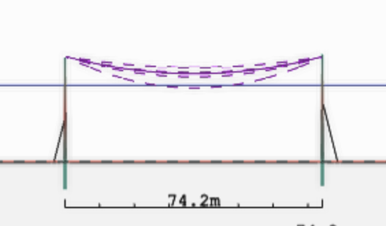
Earlier we set our standard clearance line at 5.5m. This is displayed as a blue horizontal line in the Profile view:
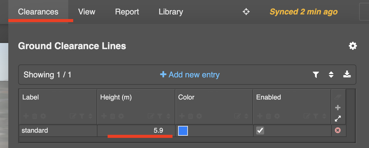
To update it select the Clearances menu and modify the height of the line we've labelled Standard from 5.5m to 5.9m:
Setting ground clearance rules
To check our ground clearances, we need to set up the Clearance Rules table. This defines the clearance requirement depending on the kV of the line and the type of object we want to measure to.
In this example we want to make sure that the ground clearance in the clearance rules is set to 5.9m.
- Select the Clearance menu
- Set 5.9m in the 11kV cell in the Ground row
- Add Hot to the Applies to environments field above the table. This is the environment that we want to check our ground clearance under.
Checking ground clearance
Neara provides two ways to check for ground clearance violations.
Using the Profile view
This is the easiest method to check for ground clearance violations.
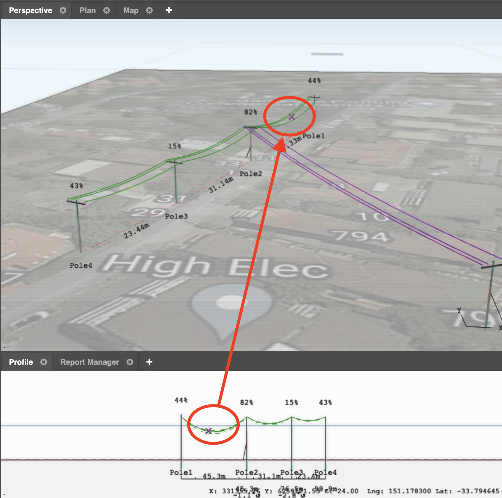
In the Profile view in the lower part of the screen, select a circuit to see areas where the conductor breaches the clearance line (in this case, the blue line):
Create a Ground Clearance Report
You can also get accurate, detailed clearance measurements by creating a Ground Clearance Report using the Neara Report builder.
- Click the (+) to the left of the Profile view tab
- In the pop-up, click Create custom report
- When prompted, select GroundClearanceReports as the data source for the report, and give your report a name e.g. Ground clearance
- Click Create
- The new report is a table that appears in a tab in the lower part of the screen, next to the Profile view
You can move that new report tab out into its own panel so that you can simultaneously see the Perspective, Profile and Ground Clearance Report views
The table in the report shows the minimum clearance of each span under the environment specified in the clearance tab, and whether it fails or passes the criteria that we have set (5.9m):
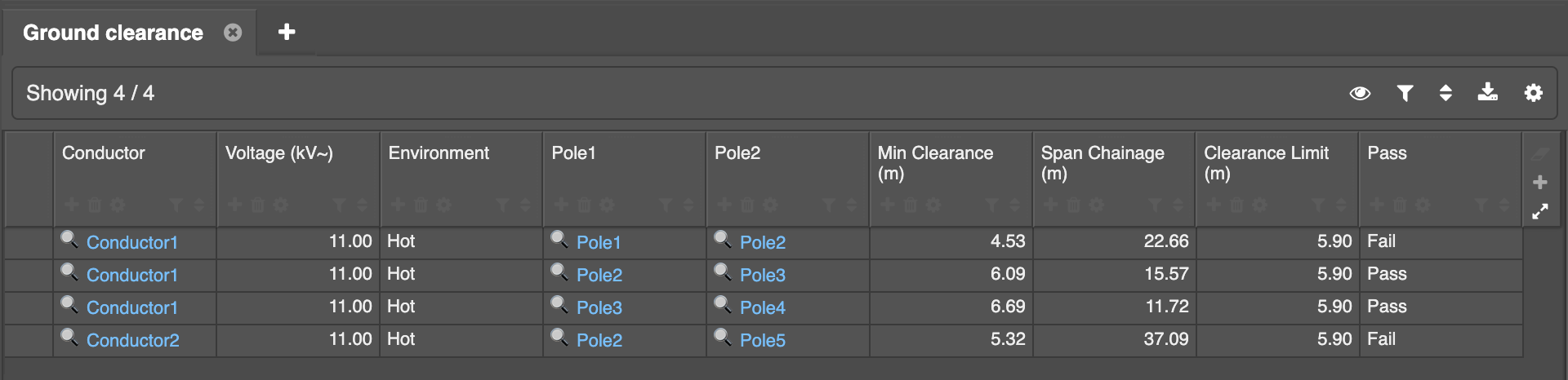
We can hide rows that Pass to allow us to focus only on the spans that are failing the clearance requirement:
- Hover the mouse over the Pass column header
- Click the Filter icon that appears under that column's title:

- In the pop-out, select to show only rows with a Fail result
To fix these clearance issues, we can replace those poles to raise the clearance of this span, or we can also increase the tension of the line.
Deleting a report
- Click the (+) to the left of the Profile view tab
- In the pop-up, click Report Manager
- In the Report Manager tab, hover over the report to delete, and click the trashcan icon that appears
- If you have moved the report tab into its own panel in the Workspace, you have the option of removing the now-empty tab and panel
Check conductor clearance to nearby objects
Since we are building in a suburban area we should check for clearances to nearby houses. Neara supports obstruction modelling with prisms, cylinders, and fences.
Create an obstruction
- Select the Obstruction tool on the toolbar
- Define the type of obstruction to place down in the properties tab: Prism, Cylinder or Fence
- Left-click to place the obstruction on the map
- To delete an obstruction, switch to the Select tool, select the obstruction, and press DEL / DELETE on your keyboard
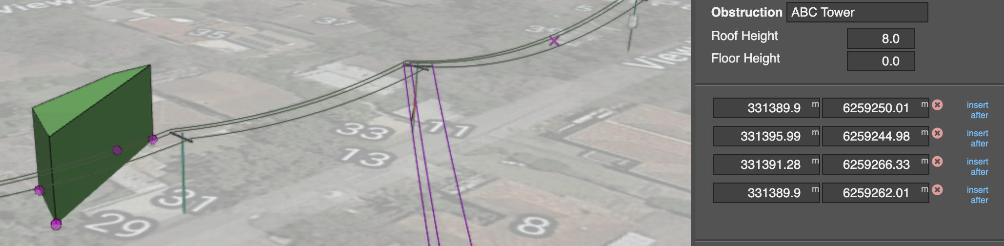
You can modify an obstruction's shape after it is placed and selected:
- Give it a more descriptive, meaningful name
- Drag its vertices to fit a general shape
- Define precise eastings and northings, and roof and floor heights in the Properties panel in the sidebar
Measuring distances
To measure the distance between a conductor and any other object including Obstructions, Poles, Another Span, select the Clearance Measure tool on the toolbar. Sag and blowout outlines will appear:
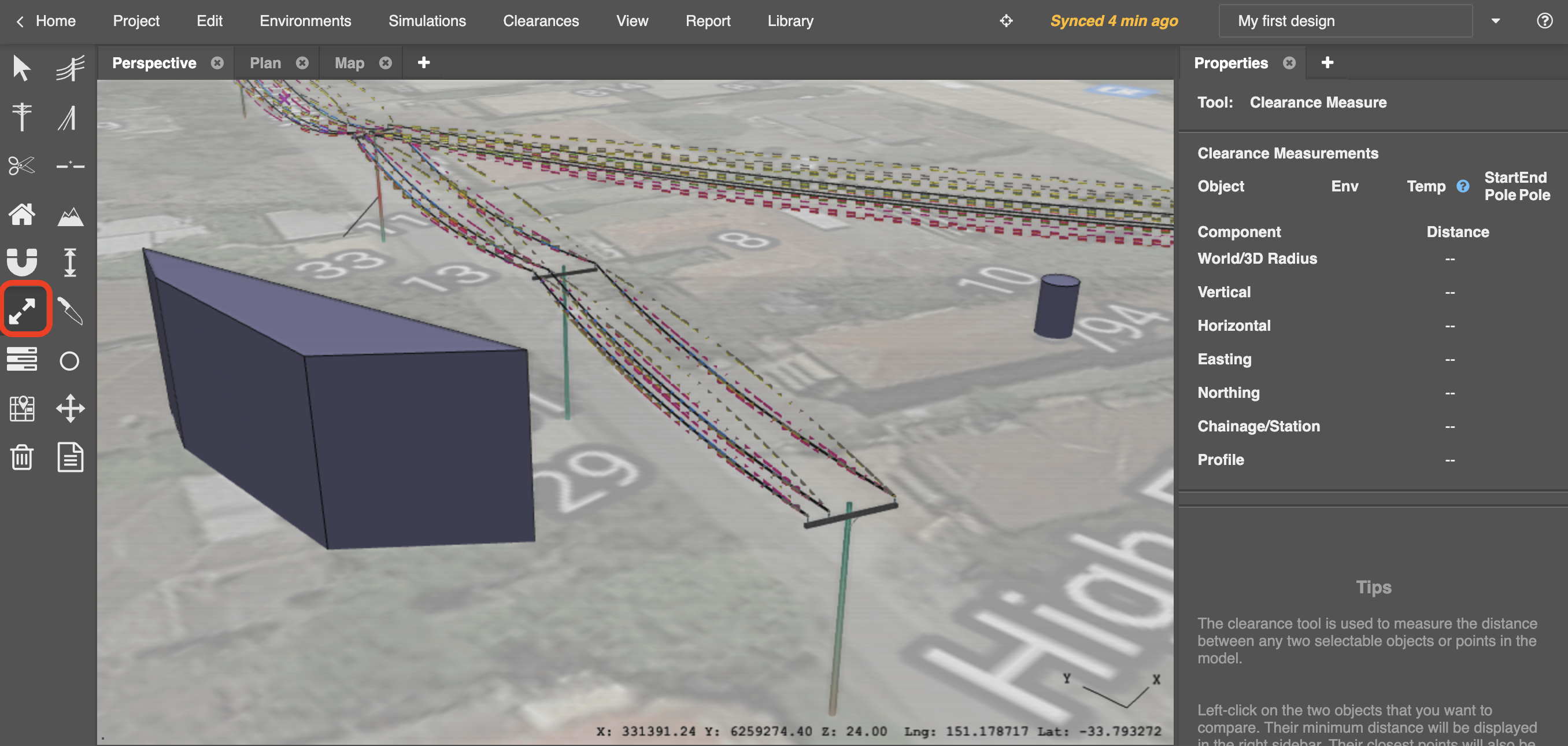
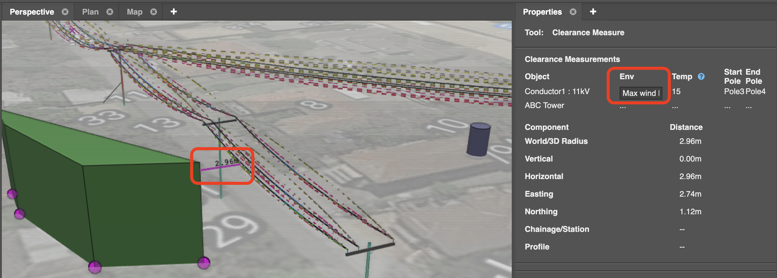
Click the conductor outline to start the clearance distance measurement (the environment of the outline will be shown in the Properties panel) and then click the object to measure to.
By default, the shortest distance between the two objects will be displayed:
See also: Modelling obstructions such as buildings and fences
Next: 7 - Exporting Reports