Sag Measurement

Written by Cody Yakimoff
Updated at November 29th, 2022
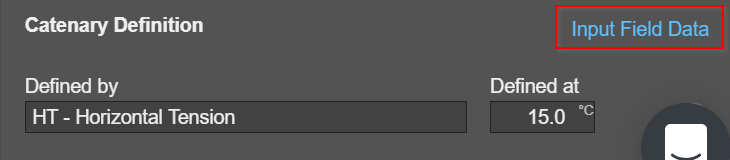
This feature can be found by selecting a conductor and then in the properties panel clicking on "Input Field Data" in the Catenary Definition section.
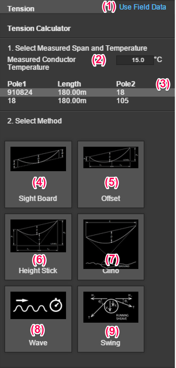
1. Use Field Data
To input sag measurements from field surveys, first select the conductor in the work space.
Then click on Use Field Data on the right hand side bar.
2. Measured Conductor Temperature (∘C)
Input the conductor temperature recorded on the day of survey.
3. Span Selection
A list of all spans within the work space will be shown here. Each span is noted with their respective pole names on each side, with the span length in the middle.
See AS7000 Appendix T for more details on the below methods.
4. Sight Board Method
The sag for the sight board method is as follows:

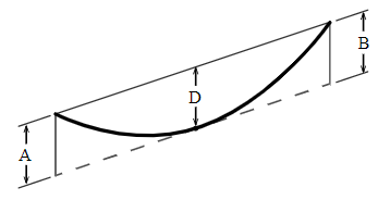
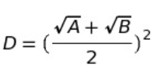
Where:
D = conductor sag at mid span
A = distance below first conductor attachment
B = distance below the second conductor attachment
5. Tangent Method 1
The sag for the Tangent Method 1 is as follows:

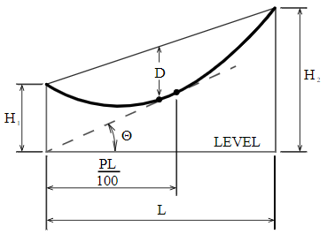
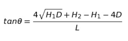
Where:
θ = angle of tangency to the catenary
D = conductor sag at mid span
H1 = vertical distance from the center of the theodolite to the conductor attachment
H2 = far attachment height of conductor above the instrument height
L = span length
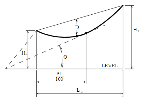
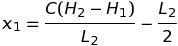
6. Tangent Method 2
The sag for the Tangent Method 2 is as follows:


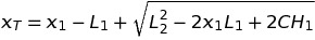

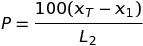
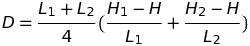
7. Offset Method
The sag for the Offset Method is as follows:

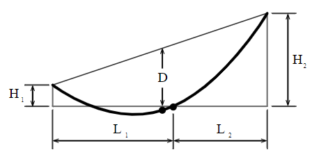
Where:
D = conductor sag at mid span
L1 = distance from center shot to LH attachment
L2 = distance from center shot to RH attachment
H1 = LH attachment height relative to center shot
H2 = RH attachment height relative to center shot
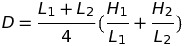
8. Height Stick Method
The sag for the Height Stick Method is as follows:
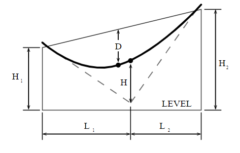

Where:
D = conductor sag at mid span
L1 = distance from center shot to LH attachment
L2 = distance from center shot to RH attachment
H = Height of conductor above instrument
(if measuring height above ground, subtract instrument height)
H1 = LH attachment height relative to center shot
H2 = RH attachment height relative to center shot
9. Clino Method
The sag for the Clino Method is as follows:

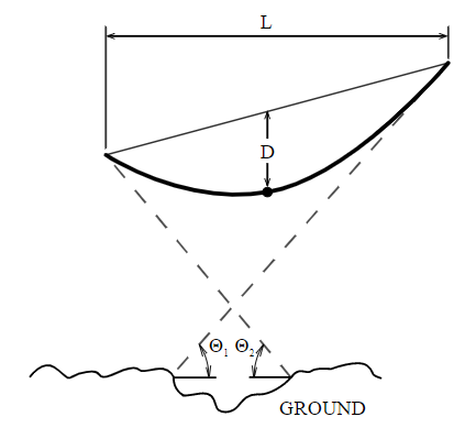
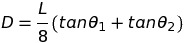
Where:
D = conductor sag at mid span
L = span length
tanθ1 = gradient to the point of tangency at one attachment point
tanθ2 = gradient to the point of tangency at the other attachment point
10. Wave Method
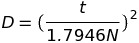
The sag for the Wave Method is as follows:
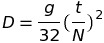

D = conductor sag at mid span
t = time (sec) for N return waves
N = number of return waves (usually three)
g = gravitational acceleration constant - 9.8067m per second squared
11. Swing Method
The sag for the Swing Method is as follows:
D = conductor sag at mid span
t = time (sec) for conductor to swing N times from one side to the opposite side and back
N = number of swings timed